According to ACI, fibre reinforced concrete is that kind of concrete made of hydraulic cements containing aggregate of various sizes and amounts and discontinuous discrete fibres (ACI Committee 544, May 1982). The fibres used have to be not more than 50mm and 500mm in length and diameter respectively. Furthermore, the volume fraction of fibres used must not exceed 2% of total volume of mix. A typical water to cement ratio used in FRC mixes is in the range of 0.35.
Fibre Reinforced Concrete is generally a very durable material regardless of the type of fibre used. Steel fibres used these days are mainly brass coated in order to avoid the corrosion problems of the past. Generally, steel fibres are well protected in uncracked concrete where the high alkalinity provides a passive layer on the fibre surface. But even in the past where non-stainless steel fibres were used serious corrosion needed many years to occur[i]. In the case of cracked concrete, fibres (if not corrosion protected) may corrode very rapidly in the presence of chlorides.
Durability
In the case of polypropylene fibres, the problems due to chemical degradation are not present since these fibres are generally chemically inert[ii]. These fibres are used mainly to improve the impact resistance of the composite. Furthermore, research work has shown that composites using polypropylene fibres retain their durability for long periods under normal working conditions[iii]. It is useful to note that polymeric fibres (polypropylene or nylon) have an essential function during the early stage strength of the mix since they prevent early shrinkage cracking due to the compatibility of their Young’s Modulus with that of concrete at early ages[iv].
Glass fibres, as it was mentioned previously, were initially found to suffer from alkaline attack. Further research on that subject led to the development of alkali resistant glass fibres. The durability of composites containing glass fibres is strongly related to the exposure environment. Under dry conditions the toughness of the composite remains almost unaffected even after a ten-year period whereas under water or natural weathering conditions the flexural strength may exhibit severe reduction[v].
Fracture Toughness and Tensile Strength
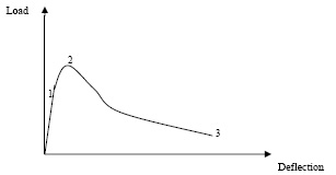
A typical load-deflection diagram for FRC is shown below.
Figure 1. Load Deflection diagram for FRC.
No matter what kind of fibre is incorporated in the concrete mix the tensile strength of the composite is only slightly greater than that of the cement matrix. Fibres have no little or no influence on the matrix behavior until first cracking. The effect of fibre reinforcement on the composite starts soon after the first crack, influencing the pre-peak strain hardening (region 1 to 2) and especially the post peak tension softening response of the matrix (region between points 2 to 3) by bridging across the microcracks and reducing their width. This enables the matrix to resist more applied load experiencing ductile response to the continuous loading and not brittle as it was previously without the reinforcement. The post first crack behavior depends on the volume fraction of the fibres used in the mix as well as on the aspect ratio of the fibres. Thus, the area under the load deflection diagram, which represents the fracture toughness, is much larger for the FRC than for the ordinary concrete. With increasing deflection, load carrying capacity drops gradually and almost linearly as a result of frictional pull-out of fibres. The increased fracture toughness and the extended strain hardening response exhibited by fibre reinforced concrete are due to the fact that fibres operate perfectly as crack arrestors, bridging the microcracks and preventing in that way their localization and the formation of a large single crack.
In order to achieve improved tensile strength it is apparent to use large volume fractions of fibre. However, if that is the case, care has to be taken to avoid mix workability problems. The marginal improvement in the tensile strength of concrete by the incorporation of fibres (unless large proportions are used) makes FRC more suitable for durability purposes, while other, more improved cementitious composites (e.g. HPFRC) are suitable for structural applications.
Load Deformation Response for Conventional FRC and HPFRC
FRC and HPFRC have similar tensile/flexural load-deflection response, which is shown in the figure below.
Figure 2. Tensile/Flexural load deformation response of conventional and high performance FRC.
Both composites exhibit linear elastic behavior until they reach point 1 on the curve. At this point the first cracks initiated. Both materials are able to resist more applied load until they reach the load carrying capacity, at point 2. This region between points 1 and 2 is termed strain hardening and it is similar in both materials. When the crack saturation point is reached (point 2) both materials exhibit the so-called strain softening response, which is the region between points 2 and 3 on the curve. Although, the load carrying capacity has been reached at point 2 failure does not takes place immediately. The localized microcracks assemble forming larger cracks, which are held by the fibre reinforcement, and progressive failure takes place in a ductile manner in both the conventional and high performance FRC.
There are however important differences between these two materials in terms of the above graph.
Since the slope of the linear part (up to point 1) is an indication for the E-value of the material it can be said that the stiffness of HPFRC is larger than that of conventional FRC. Secondly, the strain hardening region is much larger for the HPFRC in relation to the conventional one. This is because a large volume fraction of fibres has been incorporated in the mix. As a result of this, the load carrying capacity for the HPFRC is much larger, causing a larger amount of deformation, as well. This behavior indicates that HPFRC is much more ductile material. Finally, it can be observed that the energy absorption capacity GF, which is represented by the area under the curve, is much larger than the corresponding value for the conventional FRC, i.e. HPFRC is more tough due to the inclusion of long fibres (13mm in length). The following table shows the differences in the basic properties discussed above.
Table 1 Typical values for principal properties of conventional and high-performance FRC.
|
|
E
|
ft
|
GF
|
|
Conventional FRC
|
30 – 35 GPa
|
6 – 8 MPa
|
1000 J/m2
|
|
HPFRC
|
40 – 45 GPa
|
25 – 40 MPa
|
40000 J/m2
|
Workability
Generally, workability can be defined as that property of concrete, which indicates its ability to be mixed, handled, transported and placed with minimum loss of homogeneity[vi]. Furthermore, the term workability can be used in order to describe all the essential properties of early stage concrete, such as mobility, compactibility, stability and finishability[vii].
There are various ways of measuring the workability of concrete mixes. Slump is a common, fast and relatively economical test but unfortunately it does not give reliable results in the case of FRC. The compacting factor test has been used in the past but experimental evidence has shown that the success of that test is very limited3. The most reliable workability test for FRC mixes seems to be the VeBe test. This test takes into account the effect of aggregate shape, air content, admixture effects and surface friction of fibres. It is useful to notice that back in late 1970’s an alternative workability test for FRC mixes was introduced, named “inverted slump cone”[viii] but its effectiveness was questioned[ix].
The workability in FRC mixes is influenced by many factors; the most important of these are the aspect ratio and the volume fraction of the fibres used. The aggregate size and volume have also an influential role in the workability. The uniform distribution of fibres becomes more difficult as the size and volume of aggregates increase. Thus, care should be taken during the mix design in order for adequate compaction properties to achieved.
Later developments in the FRC technology, connected with the addition of superplasticisers and microsilica in the mix aim at producing a composite with reduced water to cement ratio and increased strength
[v] Illston, J.M., “Construction Materials” Second Edition, 1996, E & FN Spon, pp 392-395.
[vi] ACI Committee 544.2R-78 (Revised 1983), “Measurement of Properties of FRC”, pp 433-448.
[vii] Swamy, R.N., Stavrides, H., “Some properties of high workability steel fibre concrete”, RILEM International Symposium in Fibre Reinforced Cement and Concrete, 1975, pp 197-208.
[viii] Schrader, E.K., “Formulating guidance for testing of fibre concrete in ACI Committee 544”, RILEM International Symposium in Testing and Test Methods of Fibre Cement Composites, 1977, pp 9-21.
[ix] Tattersall, G.H., “Discussion Topics”, RILEM International Symposium in Testing and Test Methods of Fibre Cement Composites, 1977, pp 61-63.